Dpc / Power management

DZY-4850HI Equipment information & support

The DPC DZY-4850HI is an industrial-grade -48V/50A high-efficiency switch-mode rectifier module and embedded DC power system engineered for continuous telecom infrastructure support with >96% conversion efficiency.

Equipment information

Brand
Dpc
Equipment model
DZY-4850HI
Equipment type
Power management
Controller / software version
Confirm against the installed equipment
View full product specifications
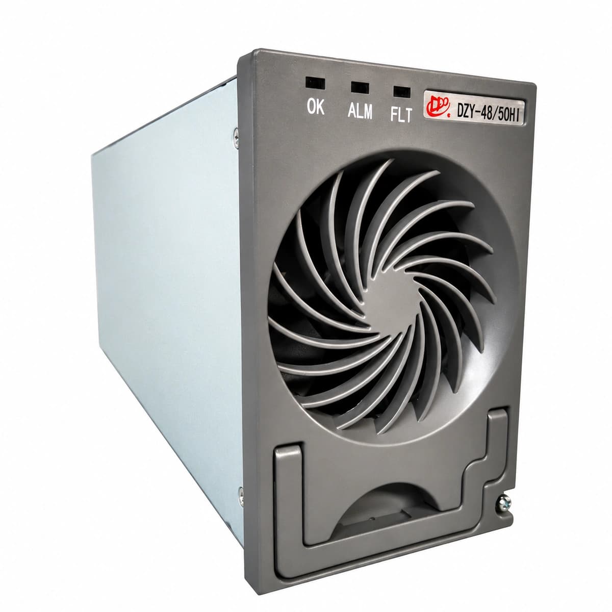
DPC DZY-4850HI Official White Background Photo View 3

Information below comes from the current product catalogue. Confirm the controller, software version and configuration of the installed equipment separately.

AC Input Voltage Range
85VAC ~ 300VAC (Nominal 220VAC) VAC
Smart Monitoring Controller
RS485 / CAN Industrial Bus Communication
Cooling Method
Built-in smart brushless DC fan cooling
Nominal Output Voltage
-48VDC (-43VDC ~ -58VDC Adjustable) VDC
Rated Output Current
50A (Full Load Power 2900W)
Managed Rectifier Capacity
High Power Density Hot-Swap Module

Alarms & troubleshooting

AC_FAIL
Yellow LED Steady, Green Run LED OFF
Mains outage, AC input breaker tripped, or AC voltage dropped below the 85VAC operational cut-off threshold.
1. Measure AC input terminal voltage with a true-RMS multimeter; 2. Inspect upstream surge protection device (SPD) and input breakers; 3. System automatically clears alarm once utility stabilizes above 95VAC.
DC_VOLT_LOW
Controller Red Alarm LED ON, Rectifier Green LED Flashing
Extended AC outage causing battery discharge below the pre-set threshold (default <45.0V), or aggregate load exceeding total rectifier output capacity.
1. Verify AC utility or initiate standby diesel generator immediately; 2. Audit active DC load currents for short circuits or unexpected equipment additions; 3. Check for failed or offline rectifier modules; 4. Prepare for impending LLVD non-priority load shedding.
REC_FAULT
Rectifier Red Fault LED Steady ON
Internal PFC/DC-DC power stage breakdown, output overvoltage latch-off, locked/failed cooling fan, or internal auxiliary bias power failure.
1. Unseat the module and inspect the rear gold-finger blind-mate connector for arc burns; 2. Check and clear any dust or debris locking the fan blades; 3. Re-seat into the slot. If the red LED persists after 60 seconds, hot-swap with a field spare and send for RMA.
BLVD_ACT
Controller Red Alarm LED Flashing, Audible Buzzer Continuous
DC bus dropped below final cut-off threshold (typically 43.2V); the battery low-voltage contactor has mechanically tripped open to protect cells.
1. DO NOT manually override or force the contactor closed, as massive inrush currents can destroy hardware; 2. Restore primary utility AC power or start mobile power generator; 3. Rectifiers will wake up and pre-charge busbar; contactor automatically resets once bus voltage surpasses 48.0V.
MOD_TEMP_HI
Yellow LED Flashing, Output Automatically Derated
Cabinet dust filter clogged, air inlet blocked, fan bearing friction/wear, or site ambient operating temperature exceeding 65°C.
1. Remove and clean cabinet air intake dust filters; 2. Clear accumulated dust from the front perforated fascia; 3. Inspect shelter HVAC system operation; 4. Check fan RPM via CSU controller; replace fan assembly if RPM falls below nominal rating.

Access Complete Maintenance & Full Alarm Troubleshooting Manual

This page lists high-frequency critical alarm codes commonly encountered in field maintenance. Comprehensive manufacturer troubleshooting matrices, board-level repair guides, detailed electrical schematics, and firmware commissioning manuals are delivered alongside equipment upon formal project procurement, accompanied by dedicated FAE technical support.

Share on-site information

  1. 01

    Identify the exact model

    Record the nameplate, system model and controller or module model.

  2. 02

    Keep the alarm details

    Record the full alarm text, indicator colour, timing and whether it persists.

  3. 03

    Describe recent changes

    Note recent replacements, software updates or configuration changes.

Record information visible in the existing interface. Electrical measurements, disassembly and replacement should follow the applicable manufacturer's manual and be performed by qualified personnel.

Your model and these details will be added to the enquiry form for you to review before sending.

Related technical articles

Browse the technical guides or send a question about this model.

View all articles

Need a replacement module or supporting equipment?

Confirm the full model, system configuration and compatibility requirements before enquiring about suitable products.

Ask about suitable products

Have a model and an on-site issue?

Share the exact model, alarm text and observed symptoms to help identify relevant information and compatibility requirements.

Request technical support