Delta / DC power systems

ESR4856G Equipment information & support

The Delta ESR4856G is a carrier-grade 1U ultra-high-density switch-mode rectifier module engineered for telecom and industrial DC power plants, delivering a nominal output of 54VDC, 56A continuous current, and 3000W maximum capacity with an energy conversion efficiency reaching 97%.

Equipment information

Brand
Delta
Equipment model
ESR4856G
Equipment type
DC power systems
Controller / software version
Confirm against the installed equipment
View full product specifications
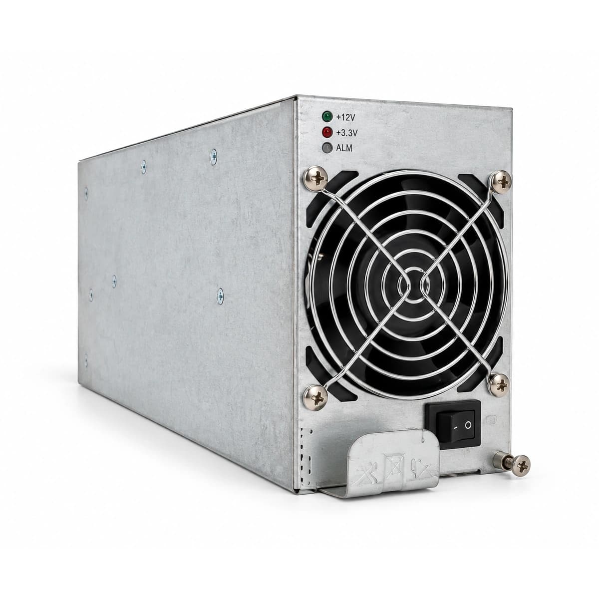
Delta ESR4856G pure white studio product shot

Information below comes from the current product catalogue. Confirm the controller, software version and configuration of the installed equipment separately.

Rated Output Voltage
-48V DC (42V~58V)
Peak Conversion Efficiency
≥ 96.0%
Operating Temperature Range
-40°C to +75°C
Cooling Method
Forced Air Cooling with Intelligent Speed Fan
Protection Features
Over-voltage, Short-circuit, Over-temperature, Surge
Hot-Swappable Support
Yes (Live Plug-and-Play Support)

Alarms & troubleshooting

AC_FAIL (AC Mains Input Failure/Out of Range)
RUN LED (Green) OFF; ALM LED (Yellow) or FAULT LED (Red) Solid ON
Utility blackout, branch breaker trip, AC phase voltage below 80VAC or above 300VAC cutoff, or loose chassis rear connector pin
1. Measure AC input terminal voltage to verify it within normal envelope; 2. Check and reset the branch miniature circuit breaker (MCB); 3. Unseat and inspect rear connector pins, then reseat firmly; 4. If AC supply is stable and reseating fails, replace module.
DC_VOLT_HIGH (DC Output Overvoltage Hardware Lockout)
FAULT LED (Red) Solid ON, module output completely gated and locked off
Internal optocoupler feedback loop failure, strong EMI on current-share bus, or hardware overvoltage comparator trip (>59.5VDC)
1. Disconnect AC input, wait 2 minutes for capacitor discharge, then re-energize; 2. If overvoltage trips immediately, internal regulation circuit is defective—replace module; 3. Verify float/boost voltage calibration in the central controller.
FAN_FAIL / OVER_TEMP (Cooling Fan Stall or Internal Thermal Runaway)
ALM LED (Yellow) Blinking continuously; cooling fan halted or abnormal acoustic noise
Airflow channel heavily clogged by dust/debris, seized fan bearing, ambient temperature exceeding +55°C, or disconnected fan tachometer signal cable
1. Extract module and clean air filters and heatsink fins; 2. Manually spin fan blades to ensure smooth rotation without friction; 3. Verify room air conditioning system; 4. If fan remains halted after cleaning, replace fan assembly or unit.
COMM_LOST (Telemetry / CAN Bus Communication Loss)
Controller screen displays 'Module Lost/Offline', module operates in autonomous fallback float mode
Oxidized gold fingers on backplane interface, improper CAN termination resistor, duplicated node ID address, or controller lockup
1. Remove module and clean rear gold-finger contacts with isopropyl alcohol; 2. Run 'Rescan Nodes' on controller GUI; 3. Verify the 120-ohm CAN termination jumper; 4. Soft reboot the central supervision unit.
SHORT_CIRCUIT / I_LIMIT (DC Short Circuit or Current Foldback Limit)
ALM LED (Yellow) Solid ON, output voltage clamped down below safety foldback threshold
Downstream DC branch cabling short-circuit, internal battery cell short, or severe inrush load current exceeding 120% rating
1. Sequentially switch off downstream DC distribution breakers to pinpoint faulted branch; 2. Disconnect battery breaker to test open-circuit terminal voltage; 3. Once external short is isolated, module recovers regulated output automatically.

Access Complete Maintenance & Full Alarm Troubleshooting Manual

This page lists high-frequency critical alarm codes commonly encountered in field maintenance. Comprehensive manufacturer troubleshooting matrices, board-level repair guides, detailed electrical schematics, and firmware commissioning manuals are delivered alongside equipment upon formal project procurement, accompanied by dedicated FAE technical support.

Share on-site information

  1. 01

    Identify the exact model

    Record the nameplate, system model and controller or module model.

  2. 02

    Keep the alarm details

    Record the full alarm text, indicator colour, timing and whether it persists.

  3. 03

    Describe recent changes

    Note recent replacements, software updates or configuration changes.

Record information visible in the existing interface. Electrical measurements, disassembly and replacement should follow the applicable manufacturer's manual and be performed by qualified personnel.

Your model and these details will be added to the enquiry form for you to review before sending.

Related technical articles

Browse the technical guides or send a question about this model.

View all articles

Need a replacement module or supporting equipment?

Confirm the full model, system configuration and compatibility requirements before enquiring about suitable products.

Ask about suitable products

Have a model and an on-site issue?

Share the exact model, alarm text and observed symptoms to help identify relevant information and compatibility requirements.

Request technical support