Delta / DC power systems

Delta DPR 48/50-G Equipment information & support

The Delta DPR 48/50-G is a carrier-grade, single-phase hot-swappable switch-mode rectifier module engineered for modern telecommunication and data networks. It converts 90V to 300V AC wide input power into stable 53.5V DC output with a rated power of 2900W (50A continuous), delivering an industry-leading peak energy efficiency of 96.2% along with active digital power factor correction.

Equipment information

Brand
Delta
Equipment model
Delta DPR 48/50-G
Equipment type
DC power systems
Controller / software version
Confirm against the installed equipment
View full product specifications
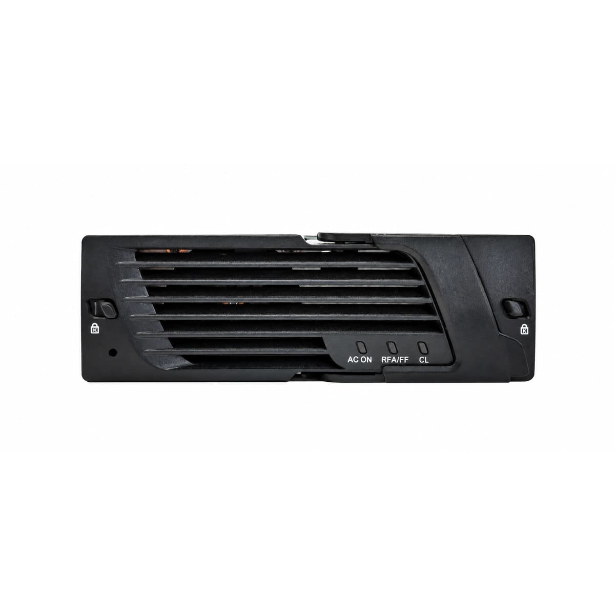
Delta DPR 48/50-G 48V 50A 2900W High Efficiency Telecom Rectifier Module Official Studio Photo 1

Information below comes from the current product catalogue. Confirm the controller, software version and configuration of the installed equipment separately.

Rated Output Power
2900W (50A @ 58V DC)
Nominal DC Output Voltage
42V DC ~ 58V DC (Nominal 53.5V DC)
Rated Output Current
50A Continuous Constant Current Output
AC Input Voltage Range
90V AC ~ 300V AC (Wide AC Input Range)
Power Conversion Efficiency
≥ 96.2% (Gold Standard High Efficiency)
Cooling Method
Built-in Intelligent Fan (Smart Noise Reduction Speed Control)

Alarms & troubleshooting

AC_FAIL (AC Input Failure / Out of Range)
Green LED OFF, Yellow/Amber LED solid ON
Utility grid blackout, AC under-voltage (<85Vac) or over-voltage (>300Vac), upstream AC breaker tripped, or loose rear AC connector
1. Measure the AC input voltage across L-N at the backplane connector with a True-RMS multimeter to confirm it is within 85Vac–300Vac. 2. Inspect the upstream AC circuit breaker (MCB) in the distribution panel and reset if tripped. 3. Pull the module, inspect the rear connector blades for arcing or mechanical damage, and firmly re-seat it into the subrack.
DC_OVP / HVSD (DC Output Overvoltage Shutdown / Lockout)
Red LED solid ON, Green LED OFF
Internal voltage control loop component failure, corrupted float/boost voltage threshold from system controller, or external bus surge exceeding hardware limit (>59.5Vdc)
1. Disengage the faulty rectifier from the shelf, wait 30 seconds for internal capacitance discharge to unlatch the HVSD circuit, then re-insert. 2. Verify the float and overvoltage settings on the CSU/Orion controller (nominal float: 53.5Vdc, HVSD cutoff: 58.5V–59.0Vdc). 3. If the module trips into red lockout immediately while bus voltage is normal, internal sensing is damaged; replace the module.
OTP / HIGH_TEMP (Over-Temperature Derating & Thermal Shutdown)
Yellow/Amber LED solid ON (derating state); Red LED solid ON, Green LED OFF (thermal shutdown state)
High ambient cabinet temperature (>65°C) caused by HVAC failure, clogged front-panel dust filters, obstructed rear exhaust vents, or heavy heatsink dust accumulation
1. Inspect site HVAC/cooling systems to ensure inlet air temperature to the subrack is maintained below 45°C. 2. Clean front-grille dust filters and clear any obstructions around the chassis air exhaust pathways using ESD-safe methods. 3. Allow the heatsink to cool down below the automatic recovery threshold (~55°C) and verify the module resumes normal output.
FAN_FAIL (Cooling Fan Failure / Rotor Blocked)
Red LED blinking or solid ON, Yellow/Amber LED ON
Foreign object obstructing fan blades, mechanical bearing seizure, broken tachometer feedback wire, or failed internal fan PWM driving circuit
1. Visually check the front airflow opening and inspect the fan blades for foreign matter or debris obstruction. 2. Disconnect and unseat the module to verify that the internal fan cable header is securely seated on the control board. 3. If the blades spin freely by hand but the fan fails to start under power or throws tach errors, replace the fan assembly or rectifier.
COMM_FAIL / CS_ERR (CAN Bus Communication Loss & Current Sharing Imbalance)
Yellow/Amber LED blinking at 1Hz, Green LED solid ON
CAN bus line disconnection between rectifier and CSU controller, oxidized/bent backplane signal pins, missing 120-ohm termination resistor, or module operating in autonomous mode causing current share imbalance
1. Reseat the rectifier to confirm signal connector pins are straight, clean, and fully engaged with the subrack backplane. 2. Verify the 120-ohm termination resistor switch/resistor presence at both physical ends of the CAN bus network. 3. Check the CSU/Orion controller menu to verify module CAN ID detection; if communication fails only in this slot/module, swap the module to isolate a hardware interface fault.

Access Complete Maintenance & Full Alarm Troubleshooting Manual

This page lists high-frequency critical alarm codes commonly encountered in field maintenance. Comprehensive manufacturer troubleshooting matrices, board-level repair guides, detailed electrical schematics, and firmware commissioning manuals are delivered alongside equipment upon formal project procurement, accompanied by dedicated FAE technical support.

Share on-site information

  1. 01

    Identify the exact model

    Record the nameplate, system model and controller or module model.

  2. 02

    Keep the alarm details

    Record the full alarm text, indicator colour, timing and whether it persists.

  3. 03

    Describe recent changes

    Note recent replacements, software updates or configuration changes.

Record information visible in the existing interface. Electrical measurements, disassembly and replacement should follow the applicable manufacturer's manual and be performed by qualified personnel.

Your model and these details will be added to the enquiry form for you to review before sending.

Related technical articles

Browse the technical guides or send a question about this model.

View all articles

Need a replacement module or supporting equipment?

Confirm the full model, system configuration and compatibility requirements before enquiring about suitable products.

Ask about suitable products

Have a model and an on-site issue?

Share the exact model, alarm text and observed symptoms to help identify relevant information and compatibility requirements.

Request technical support