Ce+T / DC power systems

CE+T 25kVA Modular Inverter Subrack Equipment information & support

The CE+T 25kVA Modular Inverter Subrack is a 19-inch heavy-duty chassis system engineered for mission-critical telecom and industrial AC power security. Designed to house parallel TSI or Bravo inverter modules, it interfaces with 48V/60V telecom battery buses and AC grid feeds, leveraging patented bidirectional power conversion to deliver zero-transfer pure sine wave power with built-in static bypass.

Equipment information

Brand
Ce+T
Equipment model
CE+T 25kVA Modular Inverter Subrack
Equipment type
DC power systems
Controller / software version
Confirm against the installed equipment
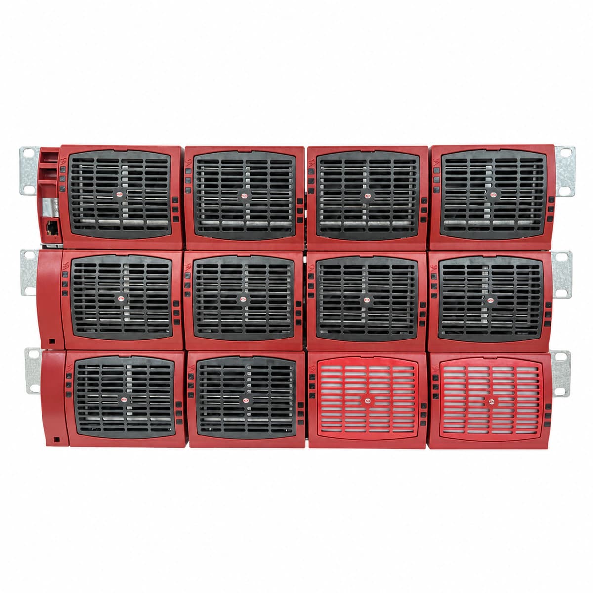
View full product specifications
CE+T 25kVA Modular Inverter Subrack (19-Inch Rackmount 48V/60Vdc to 230V/400Vac TSI/Bravo)

Information below comes from the current product catalogue. Confirm the controller, software version and configuration of the installed equipment separately.

System Output Capacity
25kVA / 20kW modular three-phase / single-phase inverter subrack
DC Input Voltage
48V DC / 60V DC telecom DC battery bus input
Physical Form Factor
19-inch standard rack-mount heavy-duty subrack (with bypass and static switch)
Rated AC Output Voltage
230V AC (single-phase) / 400V AC (three-phase) clean pure sine wave output
Inverter Module Slots
Supports hot-swappable parallel operation of multiple Bravo or TSI inverter modules
TSI Core Technology
CE+T patented TSI bidirectional power conversion (0 ms seamless transfer between AC mains and battery)

Alarms & troubleshooting

AC_MAINS_FAIL (AC Mains Input Failure / Out of Spec)
Controller Alarm LED red solid, module AC LED off, DC LED green solid
Upstream AC breaker tripped, input voltage out of operational limits, input frequency outside sync window, or incorrect phase rotation.
1. Measure line-to-line and line-to-neutral voltages at the subrack AC terminal block to verify they are within acceptable limits (185-265VAC per phase). 2. Inspect upstream distribution breakers and internal AC input breakers for trips. 3. Verify AC configuration parameters and sync tolerance settings in the Inview/T2S controller. 4. Ensure grid THD is < 5% and observe if the subrack automatically returns from pure DC battery support to normal EPC bidirectional mode.
DC_LOW_VOLT (DC Bus Under-Voltage / Approaching LVD)
Controller Alarm LED red flashing (1Hz), intermittent buzzer, module DC LED amber solid
Battery bank deeply discharged toward low-voltage cutoff, DC input fuse/breaker tripped, upstream rectifier charging failure, or excessive cable drop.
1. Immediately inspect upstream DC rectifier system and confirm float/boost charging voltages. 2. Measure DC voltage directly at the subrack rear DC busbars to verify fuses and terminal tightness. 3. Check Inview/T2S Low Voltage Disconnect (LVD) thresholds against battery OEM specifications. 4. If AC grid outage is prolonged and battery is nearly exhausted, connect a mobile generator to avoid critical inverter load drop.
INV_OVERLOAD (Inverter Output Overload / Static Bypass Transfer)
Controller Major LED red solid, module Output LED red blinking, Bypass LED green solid
Total AC load exceeds 25kVA subrack capacity, short-circuit on distribution feeder, loss of N+1 redundant module forcing remaining units into overload, or inrush load surge.
1. Check total load consumption (kVA/kW) and per-module current sharing on the Inview screen. 2. Inspect downstream AC sub-breakers and isolate any non-essential loads or faulted branch circuits. 3. Check if an inverter module has failed internally, forcing others into overload; hot-swap defective module to restore redundancy. 4. When load returns below 80% of rated capacity, clear the alarm via controller and verify automatic transfer back to pure inverter operation.
CAN_COMM_FAIL (Internal CAN Bus Failure / Sync Lost)
Controller Comm LED amber solid, module Status LED amber fast blink (2Hz), Alarm LED red on
Missing or defective CAN bus termination resistor on the backplane, bent backplane connector pins, damaged ribbon cables, or a faulty module transceiver locking the bus.
1. Verify presence and resistance of the 120-ohm CAN bus terminator jumpers on the backplane (total unpowered bus resistance should read ~60 ohms). 2. Reseat modules one by one while monitoring controller communication to isolate the specific unit pulling down the CAN bus. 3. Inspect subrack internal backplane connectors and module pins for bent pins, physical damage, or debris. 4. Check RJ45/flat interconnect communication cables between subrack slots and Inview/T2S controller; replace the rogue module if transceiver is shorted.
TEMP_HIGH (Module Over-Temperature / Thermal Shutdown)
Controller Alarm LED red solid, affected module Status/Fault LED red solid, fans running at maximum RPM
Air filters heavily clogged with dust, ambient temperature exceeds 50°C due to HVAC outage, module internal cooling fan locked/disconnected, or heat sink airflow obstructed.
1. Inspect equipment room HVAC operation to ensure intake air temperature is within nominal limits (~25°C, max 40°C continuous). 2. Clean or replace the subrack front air intake dust filters and remove any airflow obstructions at the rear exhaust. 3. Access Inview diagnostic menu to check the internal heatsink temperature readings (NTC) and fan speed telemetry. 4. If fans are stalled or heatsink remains overheated despite clean filters, hot-swap the affected inverter module for workshop maintenance.

Access Complete Maintenance & Full Alarm Troubleshooting Manual

This page lists high-frequency critical alarm codes commonly encountered in field maintenance. Comprehensive manufacturer troubleshooting matrices, board-level repair guides, detailed electrical schematics, and firmware commissioning manuals are delivered alongside equipment upon formal project procurement, accompanied by dedicated FAE technical support.

Share on-site information

  1. 01

    Identify the exact model

    Record the nameplate, system model and controller or module model.

  2. 02

    Keep the alarm details

    Record the full alarm text, indicator colour, timing and whether it persists.

  3. 03

    Describe recent changes

    Note recent replacements, software updates or configuration changes.

Record information visible in the existing interface. Electrical measurements, disassembly and replacement should follow the applicable manufacturer's manual and be performed by qualified personnel.

Your model and these details will be added to the enquiry form for you to review before sending.

Related technical articles

Browse the technical guides or send a question about this model.

View all articles

Need a replacement module or supporting equipment?

Confirm the full model, system configuration and compatibility requirements before enquiring about suitable products.

Ask about suitable products

Have a model and an on-site issue?

Share the exact model, alarm text and observed symptoms to help identify relevant information and compatibility requirements.

Request technical support